SIMULATION
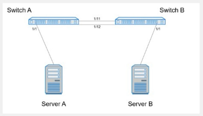
A customer must configure a peer link between two switches in the L2 MC-LAG scenario.
SwitchB has already been configured. Configure the peer link on SwitchA.
Use the following configuration information:
MC-LAG domain 1
VLAN 101
Peer link Port-Channel 100
SwitchA IP: 192.168.1.1/24
SwitchB IP: 192.168.1.2/24
MC-LAG system MAC: 00:00:00:11:11:11
The physical ports to connect the peer switch are Eth 1/5 and Eth 1/6 for each switch.
Answer : A
Here are the steps to configure the peer link on SwitchA:
Enter Configuration Mode:
SwitchA# configure terminal
Create VLAN 101:
SwitchA(config)# vlan 101
Create Port-Channel 100:
SwitchA(config)# interface port-channel 100
SwitchA(config-if-po100)# switchport mode trunk
SwitchA(config-if-po100)# switchport trunk allowed vlan 101
SwitchA(config-if-po100)# exit
Assign Physical Interfaces to Port-Channel 100:
SwitchA(config)# interface ethernet 1/5
SwitchA(config-if-eth1/5)# channel-group 100 mode active
SwitchA(config-if-eth1/5)# exit
SwitchA(config)# interface ethernet 1/6
SwitchA(config-if-eth1/6)# channel-group 100 mode active
SwitchA(config-if-eth1/6)# exit
Configure MC-LAG Domain 1:
SwitchA(config)# mclag domain 1
SwitchA(config-mclag-domain)# peer-link port-channel 100
SwitchA(config-mclag-domain)# local-ip 192.168.1.1
SwitchA(config-mclag-domain)# peer-ip 192.168.1.2
SwitchA(config-mclag-domain)# system-mac 00:00:00:11:11:11
SwitchA(config-mclag-domain)# exit
Save Configuration:
SwitchA# write memory
Comprehensive Detailed Step by Step Explanation with Reference:
Enter Configuration Mode:
Begin by entering the global configuration mode to make changes to the switch configuration.
Create VLAN 101:
Create VLAN 101 to be used for the MC-LAG peer link communication.
Create Port-Channel 100:
Enter the port channel interface configuration mode using interface port-channel 100.
Set the port channel to trunk mode with switchport mode trunk.
Allow VLAN 101 on the trunk with switchport trunk allowed vlan 101.
Exit the port channel interface configuration mode.
Assign Physical Interfaces to Port-Channel 100:
Enter interface configuration mode for ethernet 1/5 and assign it to port channel 100 using the channel-group 100 mode active command.
Exit the interface configuration mode.
Repeat the same steps for ethernet 1/6.
Configure MC-LAG Domain 1:
Enter the MC-LAG domain configuration mode using mclag domain 1.
Specify the peer link port channel with peer-link port-channel 100.
Configure the local IP address as 192.168.1.1 using local-ip 192.168.1.1.
Configure the peer IP address as 192.168.1.2 using peer-ip 192.168.1.2.
Set the MC-LAG system MAC address using system-mac 00:00:00:11:11:11.
Exit the MC-LAG domain configuration mode.
Save Configuration:
Save the configuration to ensure the changes persist after a reboot using the write memory command.
Dell Technologies Networking - SONiC
Dell Enterprise SONiC Deployment Guide
These steps provide a comprehensive guide to configure the peer link for an MC-LAG scenario on SwitchA, ensuring the specific requirements for IP addressing, VLAN configuration, and port channel setup are met.