
Get Cisco 200-601 Exam Dumps
Cisco Managing Industrial Networks for Manufacturing with Cisco Technologies Exam Dumps
This Bundle Pack includes Following 3 Formats
Test software
Practice Test
Answers (PDF)

200-601 Desktop Practice
Test Software
Total Questions : 87

200-601 Questions & Answers
(PDF)
Total Questions : 87

200-601 Web Based Self Assessment Practice Test
Following are some 200-601 Exam Questions for Review
Refer to the exhibit.
A new device, PanelView, has been added to the network. See the table for device details:
All devices are able to ping their default gateway and all other devices except PanelView. PanelView can only ping its default gateway.
After the administrator has done some investigation they have discovered the following information:
L3SW1# show run interface
interface Vlan1
no ip address
shutdown
!
interface Vlan191
ip address 10.10.27.125 255.255.255.192
ip helper-address 165.28.96.96
ip helper-address 165.28.32.235
no ip redirects
standby 191 ip 10.10.27.126
standby 191 priority 120
standby 191 preempt delay minimum 90
no ip route-cache
!
interface Vlan398
ip vrf forwarding mosaic
ip address 10.15.153.203 255.255.255.0
ip helper-address 10.15.154.252
ip helper-address 10.1.0.252
standby 98 ip 10.15.153.202
standby 98 priority 120
standby 98 preempt delay minimum 90
!
interface Vlan399
ip vrf forwarding mosaic
ip address 10.15.154.203 255.255.255.0
ip helper-address 10.1.0.252
ip helper-address 10.1.1.252
standby 99 ip 10.15.154.254
standby 99 priority 120
standby 99 preempt delay minimum 90
!
L3SW1# show ip route connected
10.0.0.0/8 is variably subnetted, 1149 subnets, 17 masks
C 10.10.27.64/26 is directly connected, Vlan191
C 10.10.31.254/32 is directly connected, Loopback1
What is preventing PanelView from pinging the other endpoints in the network?
Refer to the exhibit.
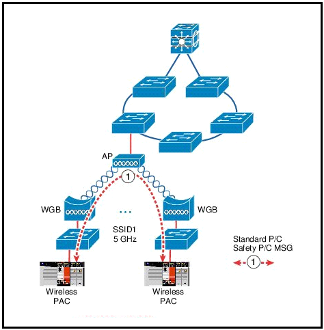
What issue does this topology present for the represented traffic flow?
Refer to the exhibit.
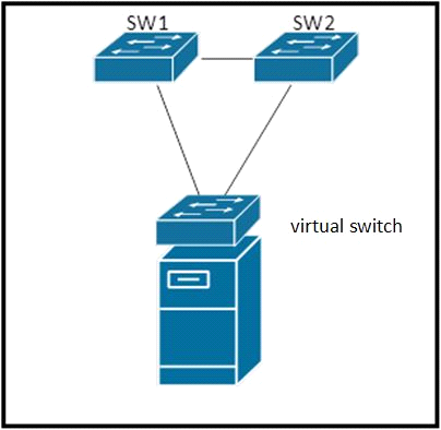
SW1, SW2 and virtual switch are connected in a loop. SW1 and SW2 are standard layer-2 switches. Which loop prevention mechanism is best suited for use within this topology?
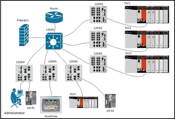
Refer to the exhibit.

All of the vlans listed in the routing table below are trunked using 802.1q and are active on all switches. PLC1, PLC2, and PLC3 each has IP address 192.168.0.1/24 and are connected to ports configured for vlan 50. L2SW1, L2SW2, and L2SW3 are not using vlan trunking for vlan 50.
L3SW1 has following routing table:
10.0.0.0/8 is variably subnetted, 12 subnets, 2 masks
C 10.3.138.0/23 is directly connected, Vlan307
C 10.3.136.0/23 is directly connected, Vlan306
C 10.15.153.0/24 is directly connected, Vlan398
C 10.3.142.0/23 is directly connected, Vlan309
C 10.3.140.0/23 is directly connected, Vlan308
C 10.3.186.0/23 is directly connected, Vlan293
C 10.15.154.0/24 is directly connected, Vlan399
C 10.3.184.0/23 is directly connected, Vlan292
C 10.3.190.0/23 is directly connected, Vlan295
C 10.3.188.0/23 is directly connected, Vlan294
C 10.3.182.0/23 is directly connected, Vlan291
C 10.3.180.0/23 is directly connected, Vlan290
PLC1, PLC2, and PLC3 cannot be reconfigured. What can be done to be able to simultaneously communicate with PLC1, PLC2, and PLC3?
Refer to the exhibit.
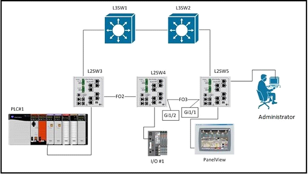
L3SW1 has a spanning-tree priority of 8192 set on VLANs 1, 300, and 301, and these VLANs are configured on and trunked between all switches. Executing the command show spanning-tree blockedports on L2SW5 results in:
L2SW5# show spanning-tree blockedports
Name Blocked Interfaces List
-------------------- ------------------------------------
VLAN0001 Gi1/1
VLAN0300 Gi1/1
VLAN0301 Gi1/1
An additional VLAN, VLAN302, is defined on all switches and trunked between them. VLAN302 access ports are set up on each of the switches and PLC#1, I/O#1, and the PanelView are attached. You expect the new VLAN to be listed as blocked on interface GigabitEthernet1/1 of L2SW5 but it is not. The three new devices are able to communicate with each other.
After executing the same command on all switches you see this output on L2SW4:
L2SW4# show spanning-tree blockedports
Name Blocked Interfaces List
-------------------- ------------------------------------
VLAN0001 Gi1/2
VLAN0300 Gi1/2
VLAN0301 Gi1/2
Why is VLAN302 forwarding on L2SW5 interface GigabitEthernet 1/1 and L2SW4 interface GigabitEthernet 1/1 and 1/2?
Unlock All Features of Cisco 200-601 Dumps Software
Types you want
pass percentage
(Hours: Minutes)
Practice test with
limited questions
Support