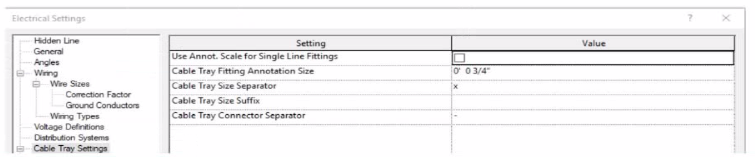
An electrical designer models a cable tray in a project and decides to check the box (or Use Annot. Scale tor Single Line Fittings and change the Cable Tray Fitting Annotation Size to 1/8" (3 mm).
What is the result?
(The image is presented m Imperial units: 1 In = 25 mm (Metric units rounded].)
Answer : A
In Autodesk Revit MEP, the Electrical Settings dialog box contains project-wide configuration parameters that affect all electrical systems, including Cable Tray Settings. This dialog allows users to control annotation scales, fitting symbols, and text size for documentation purposes.
The option labeled ''Use Annot. Scale for Single Line Fittings'' determines whether the cable tray fittings' annotation graphics automatically scale according to the view's annotation scale. When this box is checked, the annotation symbol size for fittings adjusts proportionally to the scale of the view.
Similarly, ''Cable Tray Fitting Annotation Size'' defines the annotation size for cable tray fittings in single-line representations (schematic views or simplified plan representations). Changing this parameter (for instance, from '' to '') modifies the visual representation globally for all cable tray fittings in the project, since the Electrical Settings dialog is a project-wide configuration, not a per-instance or per-view override.
According to the Autodesk Revit MEP User's Guide (Electrical Systems -- Cable Trays):
''Electrical settings define how cable trays and conduit are displayed throughout the project. Any change made to these settings, such as annotation size or use of annotation scaling, affects all related fittings and components in the project model.''
Therefore, once the designer checks the box for Use Annot. Scale for Single Line Fittings and changes the Cable Tray Fitting Annotation Size to 1/8'' (3 mm), all cable tray fittings across the entire project will update to reflect these new settings.
(The image is presented in Imperial units: 1 In = 25 mm [Metric units rounded].)
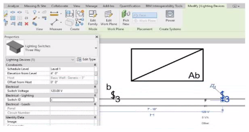
An electrical designer is trying to add the selected three-way switch to the existing switch system "b". The designer is unable to add the switch to the switch system.
Why is this problem occurring?
Answer : B
In Autodesk Revit Electrical Design, lighting control systems such as single-pole, three-way, and four-way switches are managed using Switch Systems. These systems logically connect lighting devices (switches) to the lighting fixtures they control. For multiple switches (like three-way configurations) to be part of the same control circuit, they must share the same Switch ID value.
In the exhibit, the electrical designer is attempting to add a three-way switch to the existing switch system labeled ''b'', but Revit does not allow it. The reason is that the Switch ID parameter of the new switch does not match the Switch ID of the system it is intended to join.
The Switch ID acts as the unique identifier that links all switches controlling the same group of fixtures. If the IDs differ (for example, ''b3'' versus ''b''), Revit interprets them as belonging to separate systems and prevents them from being grouped together.
The Autodesk Revit MEP User's Guide -- Electrical Systems: Lighting and Switch Systems explains this clearly:
''Switch systems are organized by Switch ID. All switches controlling the same lighting circuit must have identical Switch ID values. Revit will not allow a switch to be added to an existing system if its Switch ID does not match that system's identifier.''
To fix this, the designer must:
1 Select the three-way switch.
2 In the Properties palette, locate the Switch ID parameter.
3 Change its value to match the target switch system's ID (in this case, ''b'').
Once both switches share the same Switch ID, Revit will successfully include them in the same Switch System.
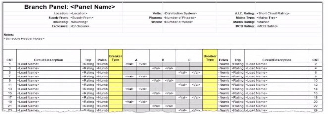
An electrical designer wants to report Breaker Type for each breaker in a panel schedule. The designer adds a column to the schedule as shown (and highlighted) in the image.
Which type of parameter should the designer create to add to the column?
Answer : C
In Autodesk Revit Electrical Design, panel schedules display data that originates from the Electrical Circuits category, not directly from the Electrical Equipment or Electrical Fixtures families. Each circuit in a panel schedule represents an instance of an Electrical Circuit object within Revit's system-based MEP structure. Therefore, to add an additional field like Breaker Type, the parameter must be created and assigned specifically to the Electrical Circuits category.
According to the Revit MEP User's Guide -- Chapter 50 ''Electrical Systems and Panel Schedules'':
''Panel schedules display parameters that are associated with electrical circuits, including load names, rating, poles, and breaker information. To include additional circuit information in a panel schedule, create a Project Parameter assigned to the Electrical Circuits category.''
This means the designer should:
1 Open Manage Project Parameters Add
2 Create a Project Parameter named Breaker Type
3 Assign it to the Electrical Circuits category
4 Set it to appear in schedules and tags, ensuring it becomes available for use in the panel schedule template
As noted in the Smithsonian Facilities Revit Template User's Guide:
''Custom circuit data fields such as 'Breaker Type' or 'Wire Tag' are defined as project parameters applied to the Electrical Circuits category so they can be displayed in panel schedule templates.''
Incorrect options:
A . Shared Parameter in Electrical Equipment --- Electrical Equipment holds overall panel data (e.g., Mains Rating, Voltage) but not per-circuit data.
B . Shared Parameter in Electrical Fixture families --- Fixtures are individual load devices, not part of the circuit's breaker assignment.
D . Project Parameter assigned to Electrical Equipment --- would apply to the panelboard as a whole, not to individual breakers in circuits.
Thus, the correct answer is C. Project Parameter assigned to Electrical Circuits, ensuring each breaker in the panel schedule can display its type individually and dynamically.
References:
Autodesk Revit MEP User's Guide -- Chapter 50 ''Electrical Systems and Panel Schedules,'' pp. 1134--1142
Which Revit command is used to map a Keynote Table file?
Answer : D
The correct command in Revit used to map (assign or browse to) a Keynote Table file is Keynoting Settings.
In Revit, keynotes are driven by an external keynote table, typically a tab-delimited TXT file that must be assigned (mapped) in the project so keynote tags can read values correctly. The official Autodesk Revit MEP documentation clearly identifies that the Keynoting Settings dialog is where this mapping is performed.
From the documentation:
To access the Keynoting Settings dialog, the instructions state:
''click Annotate tab Tag panel drop-down (Keynoting Settings).''
Regarding keynote table file location mapping:
''Keynote Table --- Full Path displays the entire path of the keynote file... Saved Path displays the file name of the keynote file that is loaded.''
It goes further to explain file path types:
''Absolute identifies a specific folder... Relative finds the keynote file where the project file... is located... At Library Locations finds the keynote file where the stand-alone installation or network deployment specified.''
The command is explicitly referenced again when fixing a missing mapping:
''Unable to Load Keynote data. Check keynote table locations in Keynoting Settings.''
''To specify the location of the keynote text file... click (Keynoting Settings).''
Other listed options do not perform keynote file mapping:
Keynote Manager does not exist as a command in native Revit.
Element Keynote is a tagging method.
Keynote Legend only displays already-mapped keynote information.
Which feature shows which user created 3n element?
Answer : B
In Autodesk Revit, the Worksharing Display Modes feature allows designers to visually inspect ownership and editing information about elements in a workshared model.
According to the Autodesk Revit MEP User Guide -- Chapter 54 ''Working in a Team'':
''Worksharing Display Modes can be used to visualize the ownership of elements, including which user created or modified them. For example, you can use the Worksharing Display command to show elements by their owner, workset, or checkout status.''
Thus, this mode identifies which user created or owns an element --- making B. Worksharing display modes the correct choice.
Other options:
A . Gray Inactive Worksets: Only shows non-active worksets in gray, not creator info.
C . Show History: Displays synchronization comments, not element ownership.
D . Worksets dialog: Shows ownership of worksets, not individual elements.
Unlock All Features of AutoDesk RVT_ELEC_01101 Dumps Software
Just have a look at the best and updated features of our RVT_ELEC_01101 dumps which are described in detail in the following tabs. We are very confident that you will get the best deal on this platform.
Select Question Types you want
Set your desired pass percentage
Allocate Time (Hours: Minutes)
Create Multiple Practice test with limited questions
Customer Support
Latest Success Metrics For actual RVT_ELEC_01101 Exam
This is the best time to verify your skills and accelerate your career. Check out last week's results, more than 90% of students passed their exam with good scores. You may be the Next successful Candidate.
95%
Average Passing Scores in final Exam
91%
Exactly Same Questions from these dumps
90%
Customers Passed AutoDesk RVT_ELEC_01101 exam
OUR SATISFIED CUSTOMER REVIEWS
Charlie
July 21, 2026
I wish to express thank PremiumDumps very much for being here. I passed AutoDesk RVT_ELEC_01101 test with a good score!
Emily Johnson
July 19, 2026
I was so afraid even to attempt AutoDesk RVT_ELEC_01101 exam, but then fortunately Premiumdumps happened to me like a blessing. I only prepared for the exam, for a week only and performed like an expert. Premiumdumps offered actual dumps to prepare for my certification exam in easy formats. I am really thankful to Premiumdumps for achieving success in my career.
Ava Grace
July 17, 2026
When I got enrolled in AutoDesk RVT_ELEC_01101, I was told that Premiumdumps is the only key to all of my worries regarding my Exam. I scored well and it justifies the standard of Premiumdumps
Devers
July 15, 2026
I was told that PremiumDumps is the solution to all of my worries regarding AutoDesk RVT_ELEC_01101 test. I obtained 98% score and it justifies the reputation of PremiumDumps.
Kenji Sato
July 13, 2026
The AutoDesk RVT_ELEC_01101 certification exam is very tough, and it was a challenging task to pass it. When I attempted it first time I couldn’t pass the exam, but then my colleague recommended me Premiumdumps exam material. The Premiumdumps offers best quality features, which enabled me to clear exam with exceptional grades.
Jacinda Ardern
July 11, 2026
I have recently passed AutoDesk RVT_ELEC_01101 exam with the excellent results, on the first attempt. I owe thanks to Premiumdumps, who helped to become certified Professional.
James Henry
July 9, 2026
Premiumdumps made me self-confident and assured with success. Its real exam simulation and self assessment tools helped me to pass RVT_ELEC_01101 exam with good grades.